Ringlock Scaffolding System
A versatile system that adapts to every shape of industrial structures.
- 42 components
- 155 size options
- Ø48,3 mm Tube
- 50 cm Rosette spacing
About the Ringlock Scaffolding System
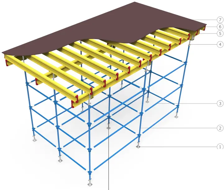
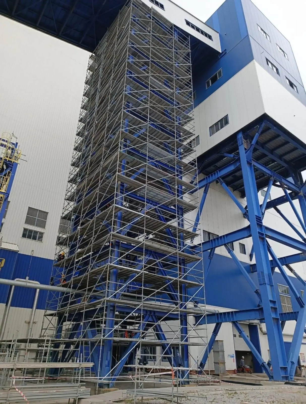
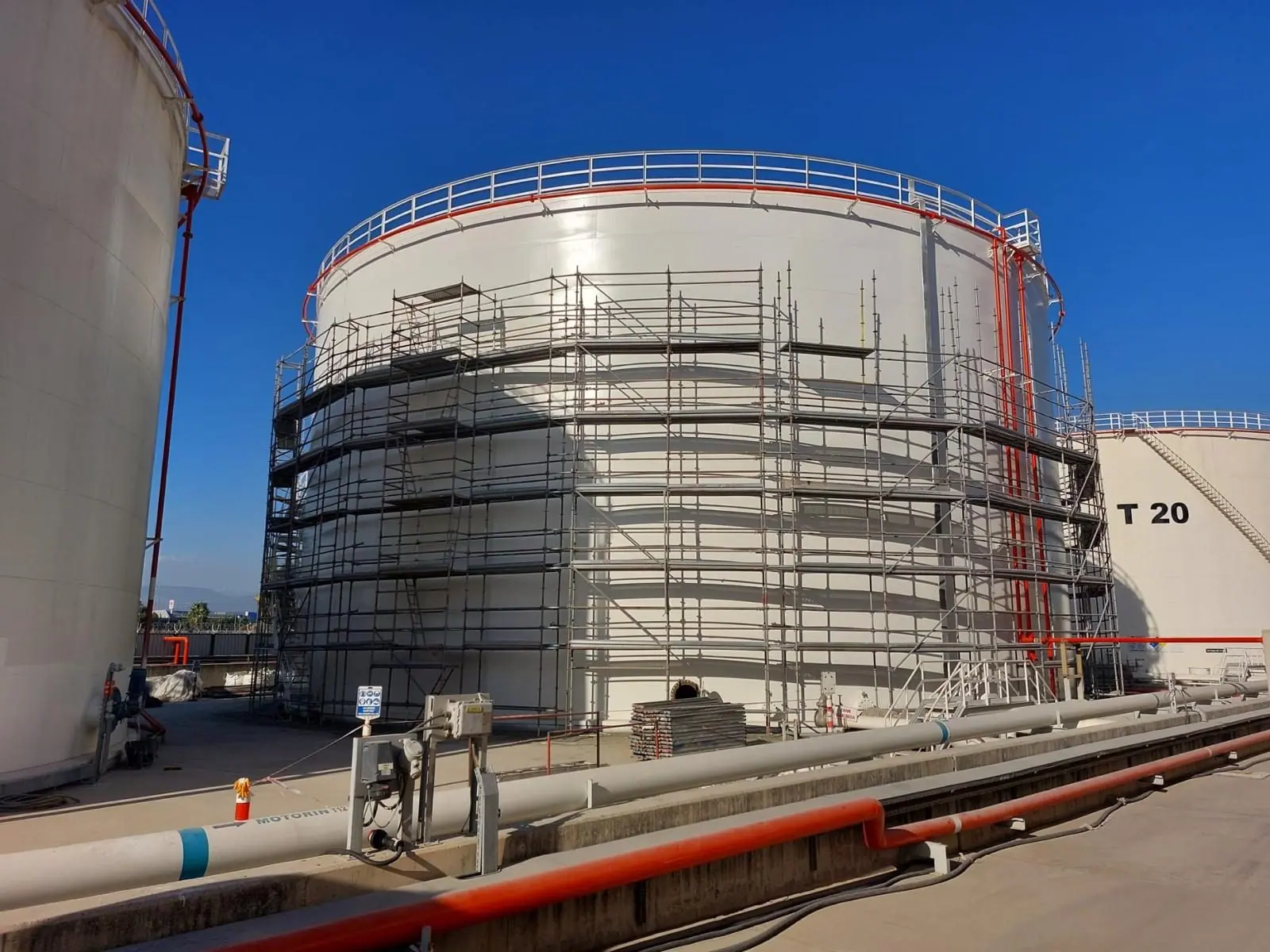
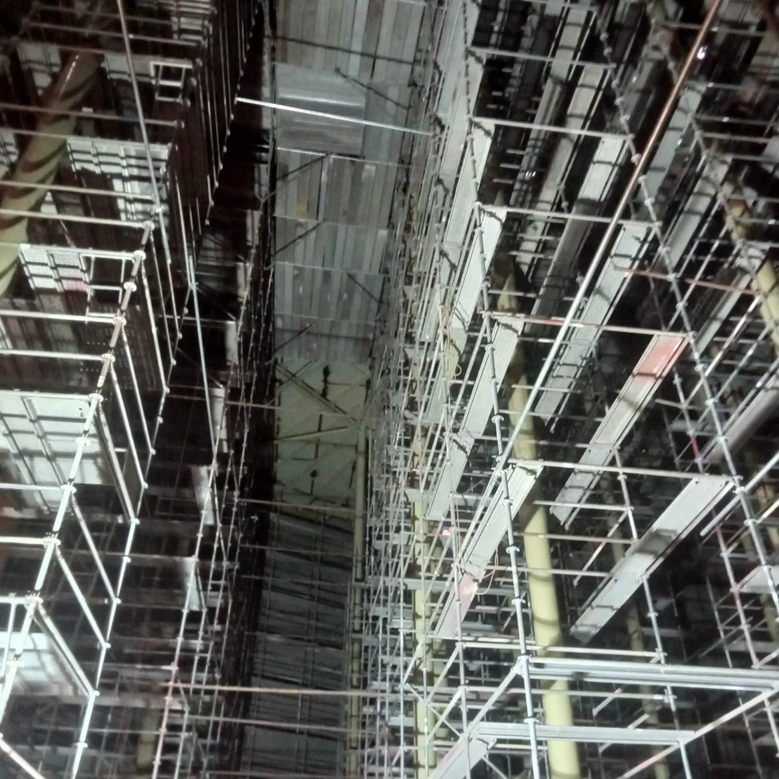
BLC Ringlock Scaffolding is a versatile system for power plants, shipyards, refineries, civil structures, tunnels and dams as well as all kinds of facade work. Up to 8 horizontal or diagonal members can be connected from different directions to the eight-hole rosettes welded on the standards, giving 360° flexibility to adapt to recesses, projections and circular surfaces. It can be used both as shoring and as working scaffold.
Key features
- Ø48 mm TSE certified, mechanically tested tubes
- ISO 9001 compliant robotic welding
- 8 connections per rosette, 360° flexibility
- Up to 6 tons load capacity per standard
- Wedge-locked, bolt-free fast assembly
- Stair towers, heavy duty and circular solutions
System components
Click a component for its size and weight table.
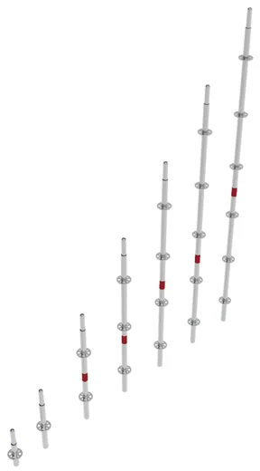
Standard (With Spigot)
25–300 cm · 1.9–13.3 kg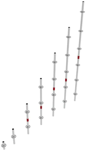
Standard
25–300 cm · 1.4–12.7 kg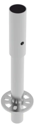
Base Collar
2.4 kg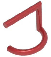
Base Collar Safety Lock
0.3 kg
Base Jack Ø38
50–100 cm · 2.8–4.5 kg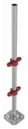
Base Jack Ø38 + Nut
70–100 cm · 3.8–4.7 kg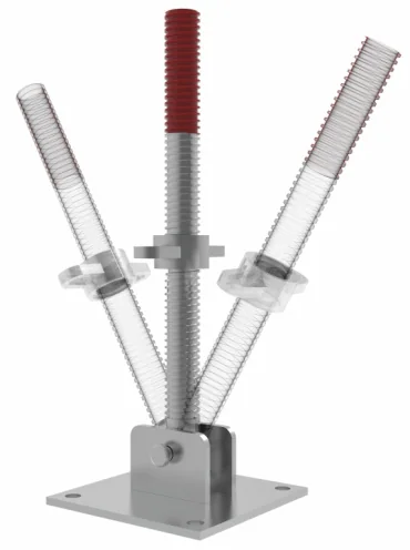
Articulated Base Jack Ø38
50–100 cm · 4.2–6.4 kg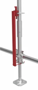
Base Jack Hook
2 kg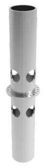
Scaffold Connection Ø38
0.55 kg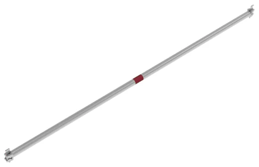
Ledger
42–300 cm · 1.9–9 kg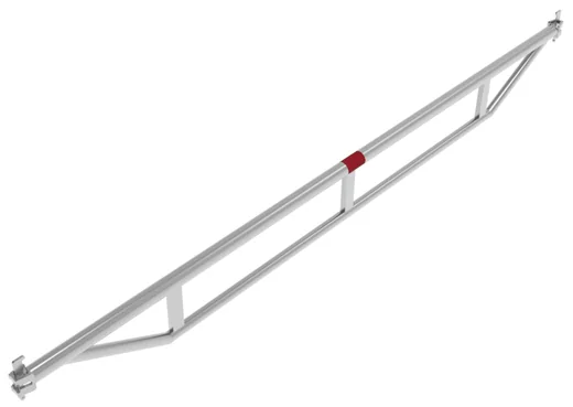
Support Ledger - B
137–300 cm · 6.3–13.5 kg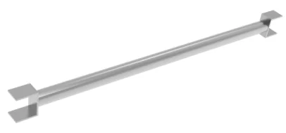
Intermediate Ledger UU
65–155 cm · 2.5–5.1 kg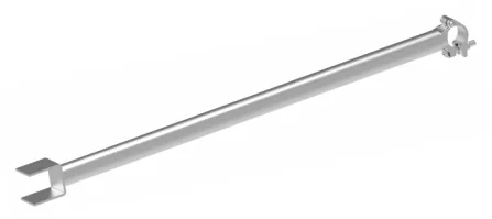
Intermediate Ledger UC
65–155 cm · 2.6–5.2 kg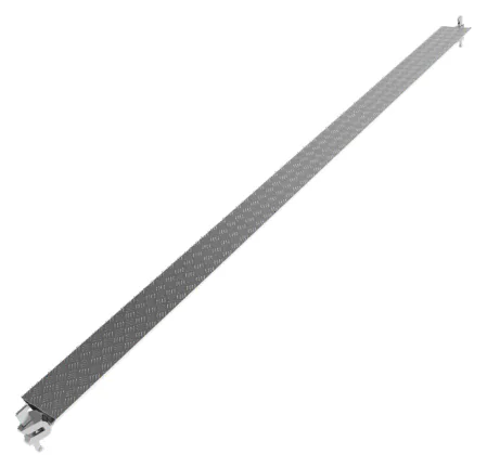
Infill Ledger
150–300 cm · 9.3–16 kg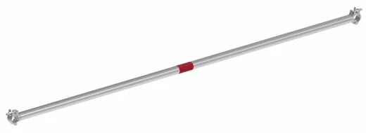
Coupler Ledger
250 cm · 7.9 kg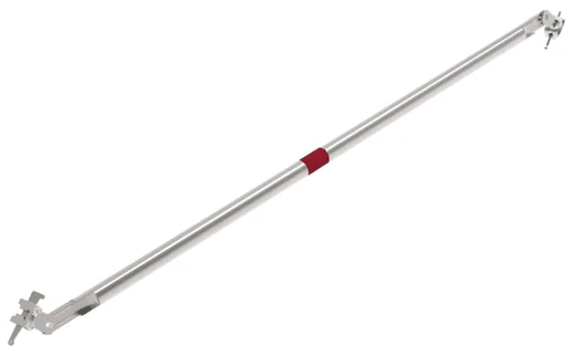
Diagonal
75×150 … 300×200 · 5.7–10.7 kg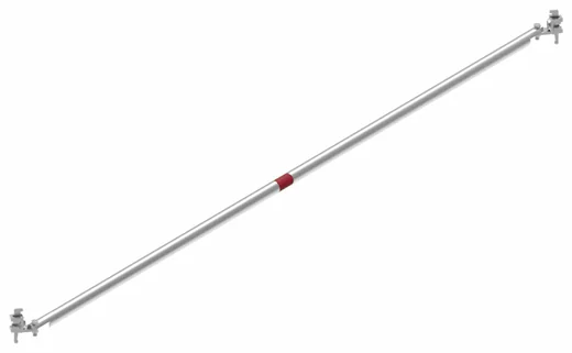
Base Diagonal
75×250 … 300×300 · 7.5–13 kg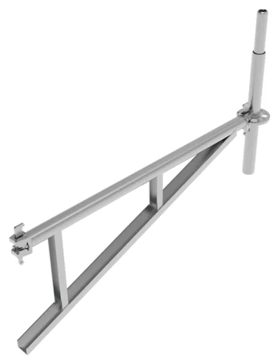
Console T1
42–111 cm · 4.5–11.9 kg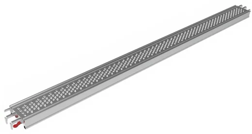
Steel Deck 18
75–300 cm · 4.8–14.2 kg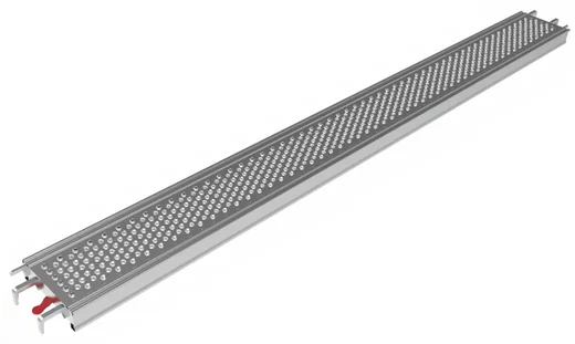
Steel Deck 23
75–300 cm · 5.2–16.4 kg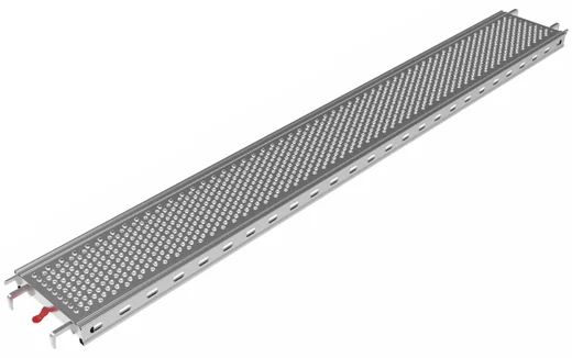
Steel Deck 32
75–300 cm · 6.3–19.1 kg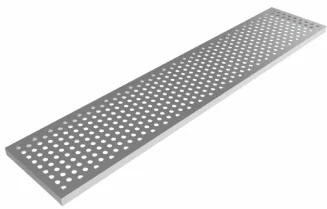
Infill Deck 30
100–250 cm · 6.6–14.5 kg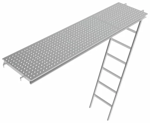
Steel Ladder Deck 63
125–300 cm · 25–45 kg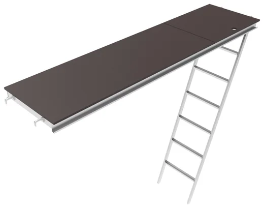
Aluminium Ladder Deck 63
125–300 cm · 19–25 kg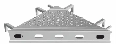
Triangle Deck
40–65 cm · 4.5–7.9 kg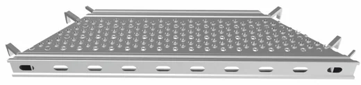
Corner Deck
125–375 cm · 8.75–22.3 kg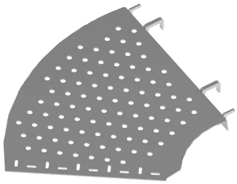
Adjustable Corner Deck
70 cm · 11.5 kg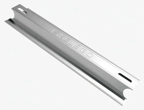
Toe Board
42–300 cm · 1–6.7 kg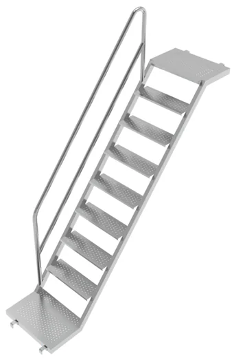
Z Type Ladder + Guard Rail
58×250×200 … 68×250×200 · 50–56 kg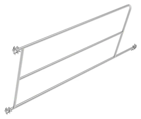
Stairtower End Guardrail
250×100 · 13.4 kg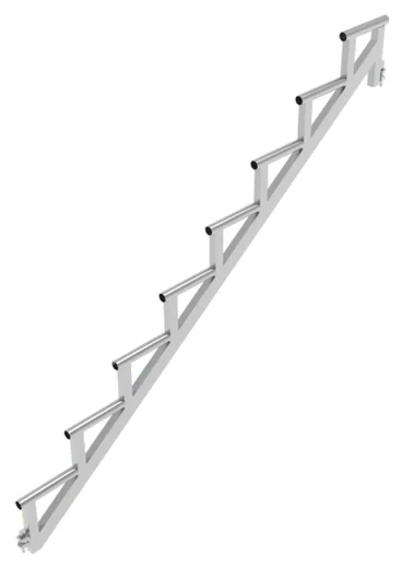
Stair Main Beam
250×200 · 28 kg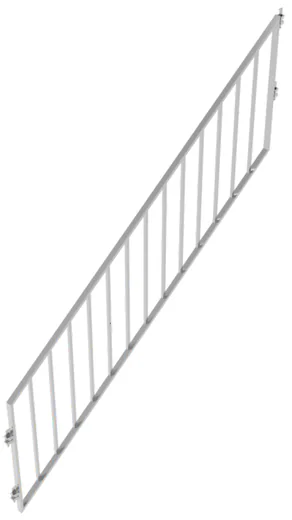
Stair Guard Rail
250×100 · 29.4 kg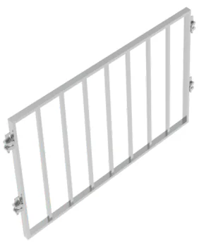
Deck Guard Rail
75×100 … 150×100 · 10.8–16.9 kg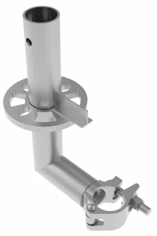
Coupler L Connector
2.4 kg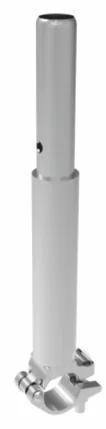
Coupler Connector
1.8 kg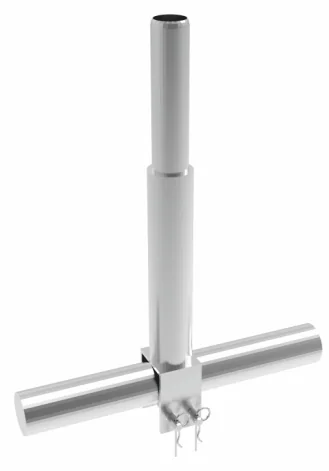
U Connector
1.8 kg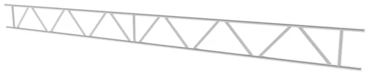
Aluminium Truss Beam
350–750 cm · 13.8–26.4 kg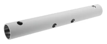
Truss Beam Connection Component
0.65 kg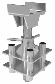
Heavy Duty Head Jack
33 kg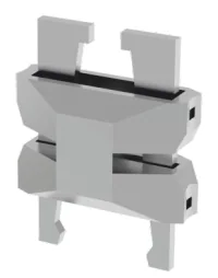
Twin Wedge Head
1.1 kg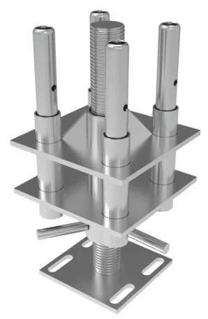
Heavy Duty Base Jack
28 kg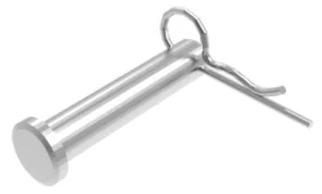
Pin and Split Pin
10×65 … 16×80 · 0.06–0.15 kgErection sequence
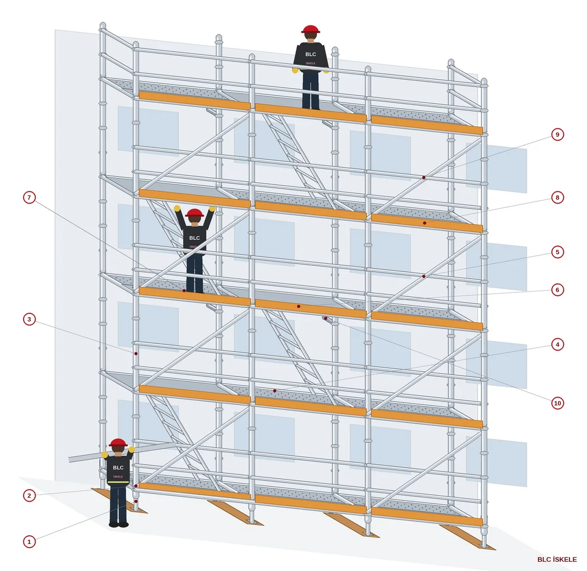
General view
- Base Jack
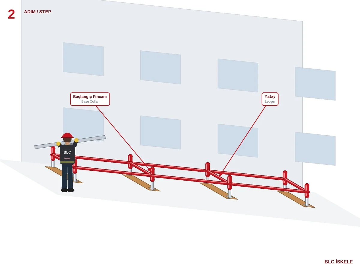
- Base Collar
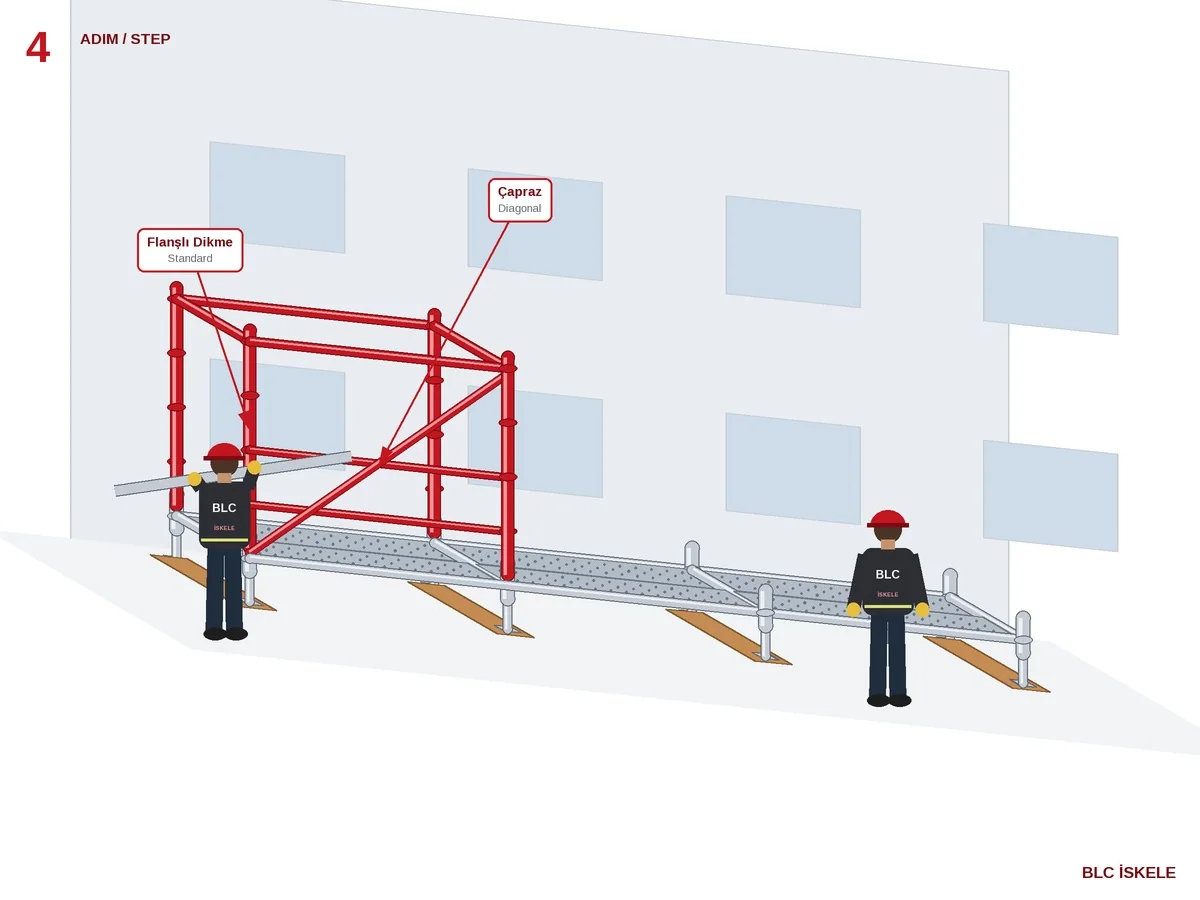
- Standard
- Ledger
- Diagonal
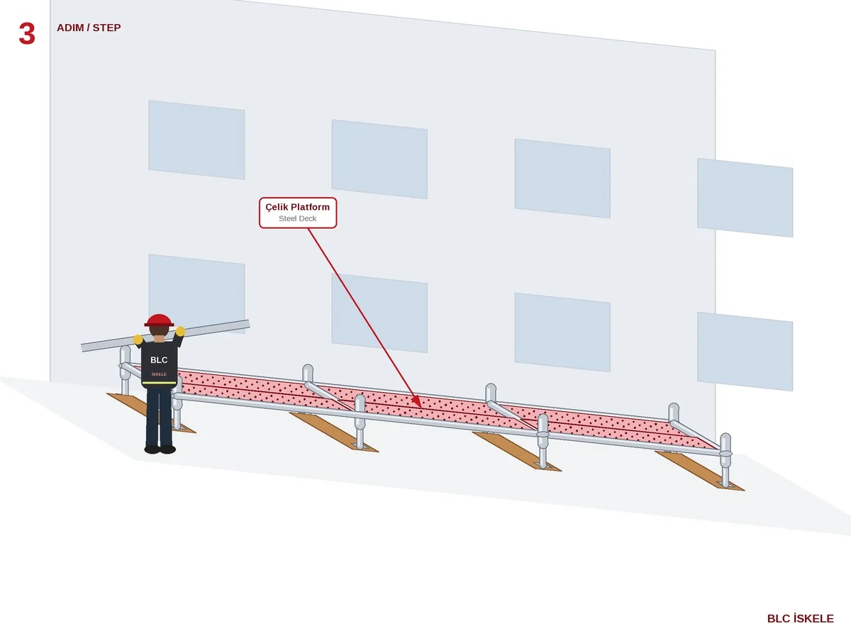
- Steel Deck
- Ladder Deck
- Toe Board
- Guardrail Ledger
- Wall Tie
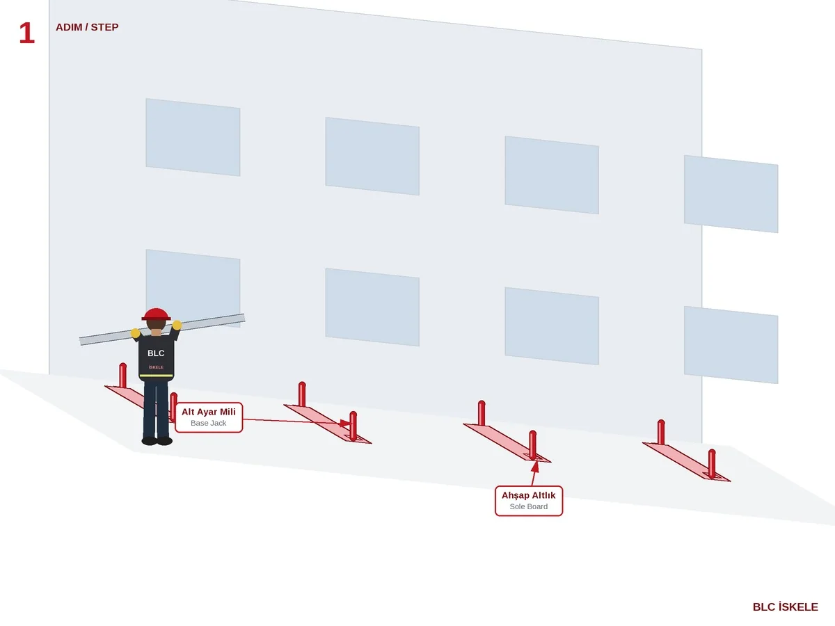
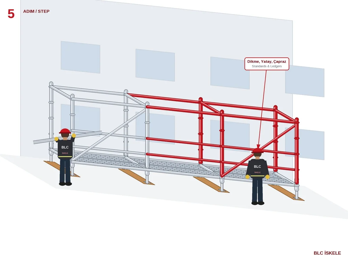
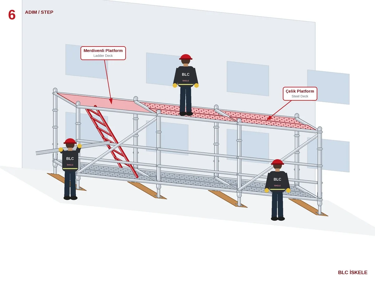
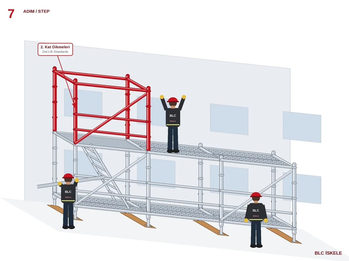
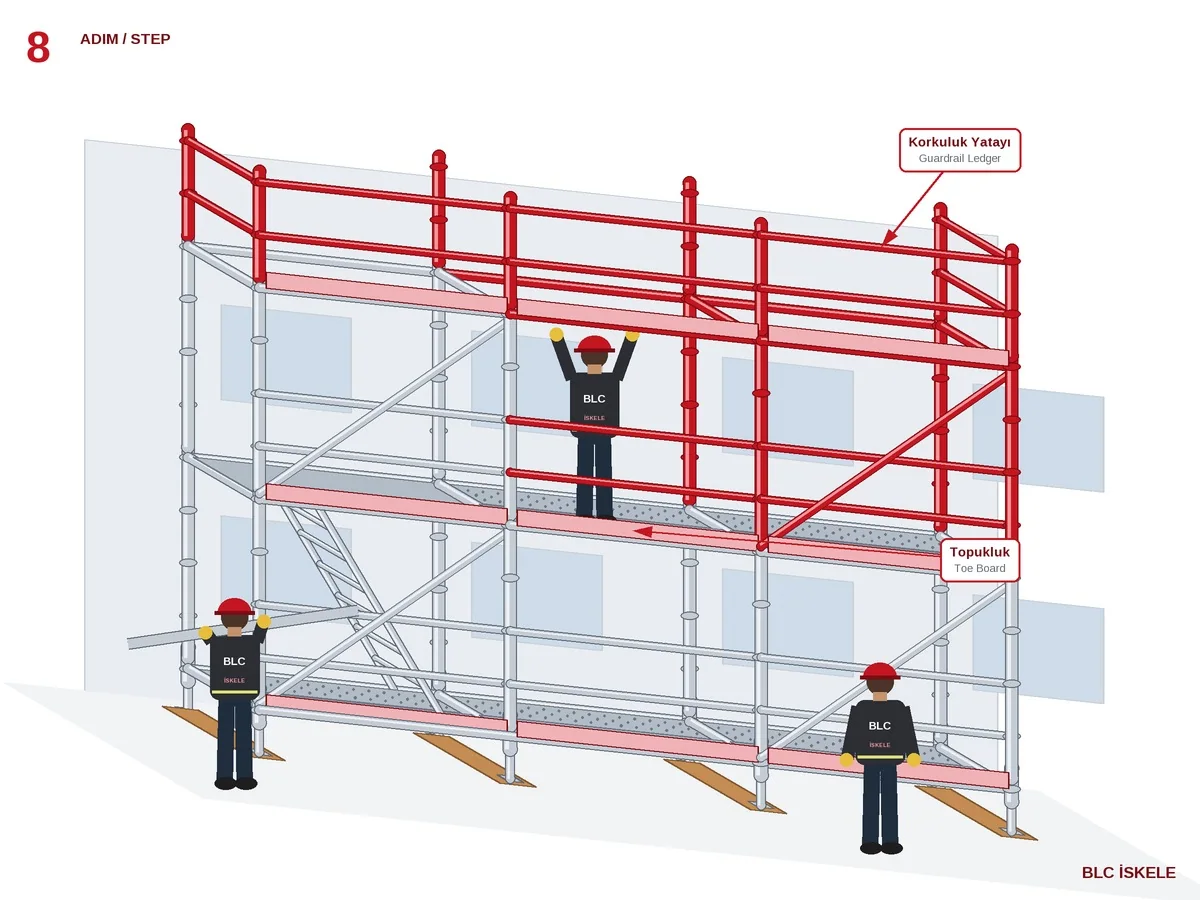
- Position and height of the base jacks are set according to the scaffolding plan.
- Base transoms are placed on the jacks, spacing is fixed with ledgers and the system is levelled.
- Decks are placed at the base level in the bays where ladder access will be provided.
- The first bay is formed with the vertical members, ledgers and the diagonals specified in the design.
- The first lift is completed in the same way.
- Upper decks are placed, observing the positions of the ladder decks.
- The first bay of the second lift is formed with vertical members, ledgers and diagonals.
- The second lift is completed; toe boards and guardrails are fitted.
- The scaffold is tied to the facade at the intervals given in the design.
- Erection continues in the same sequence up to the required height.
Application notes
- Wedges of ledgers and diagonals must be fully driven home with a hammer.
- Up to 8 connections can be made per rosette; diagonals are fitted in the bays shown in the design.
- For shoring use, standard loads must be verified by structural calculation.
- Erection, dismantling and modifications must only be carried out by trained, certified crews according to the approved design.
- Damaged, deformed or incomplete components must never be used.
- The ground must be level, firm and capable of carrying the loads.
- The system must be inspected by a competent person after erection, at regular intervals, after any modification and after adverse weather.
- Local regulations and occupational health & safety rules must be followed.

Ringlock Scaffolding System catalogue
System introduction, size and weight tables of all components, erection sequence and technical data in a single PDF. Turkish / English.
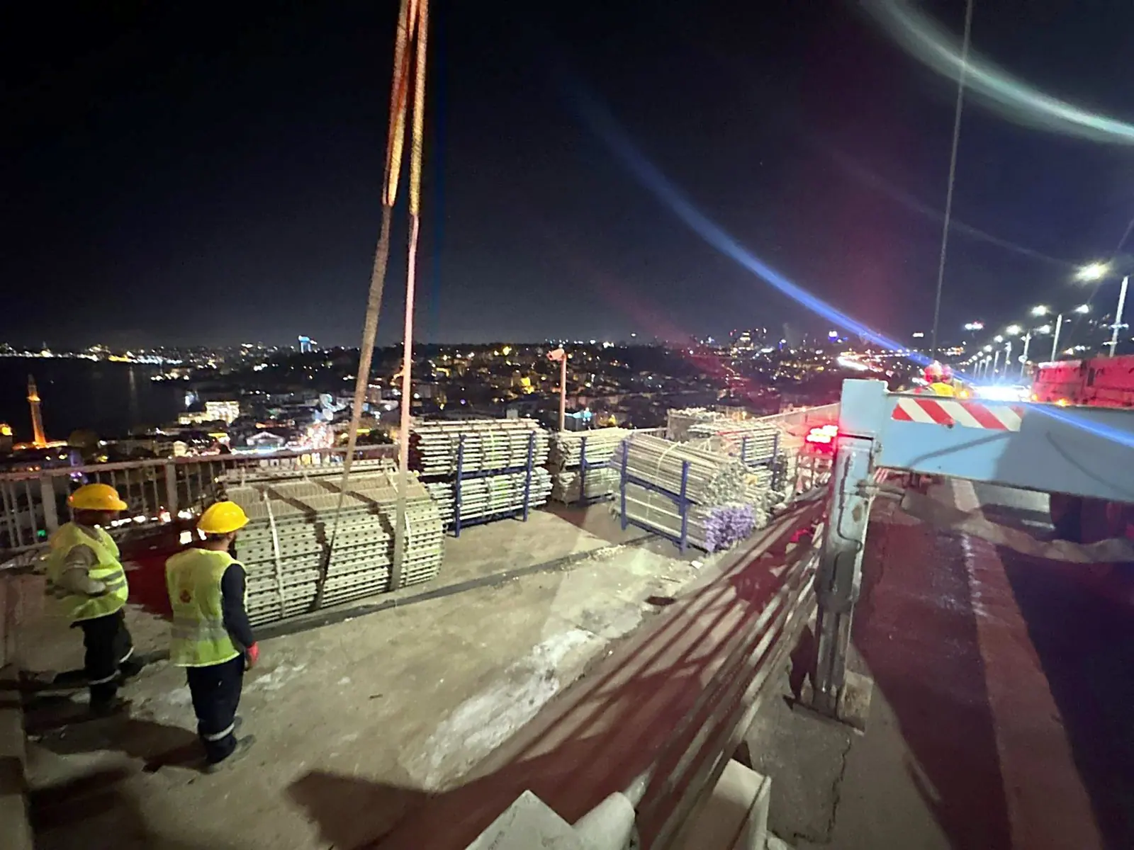
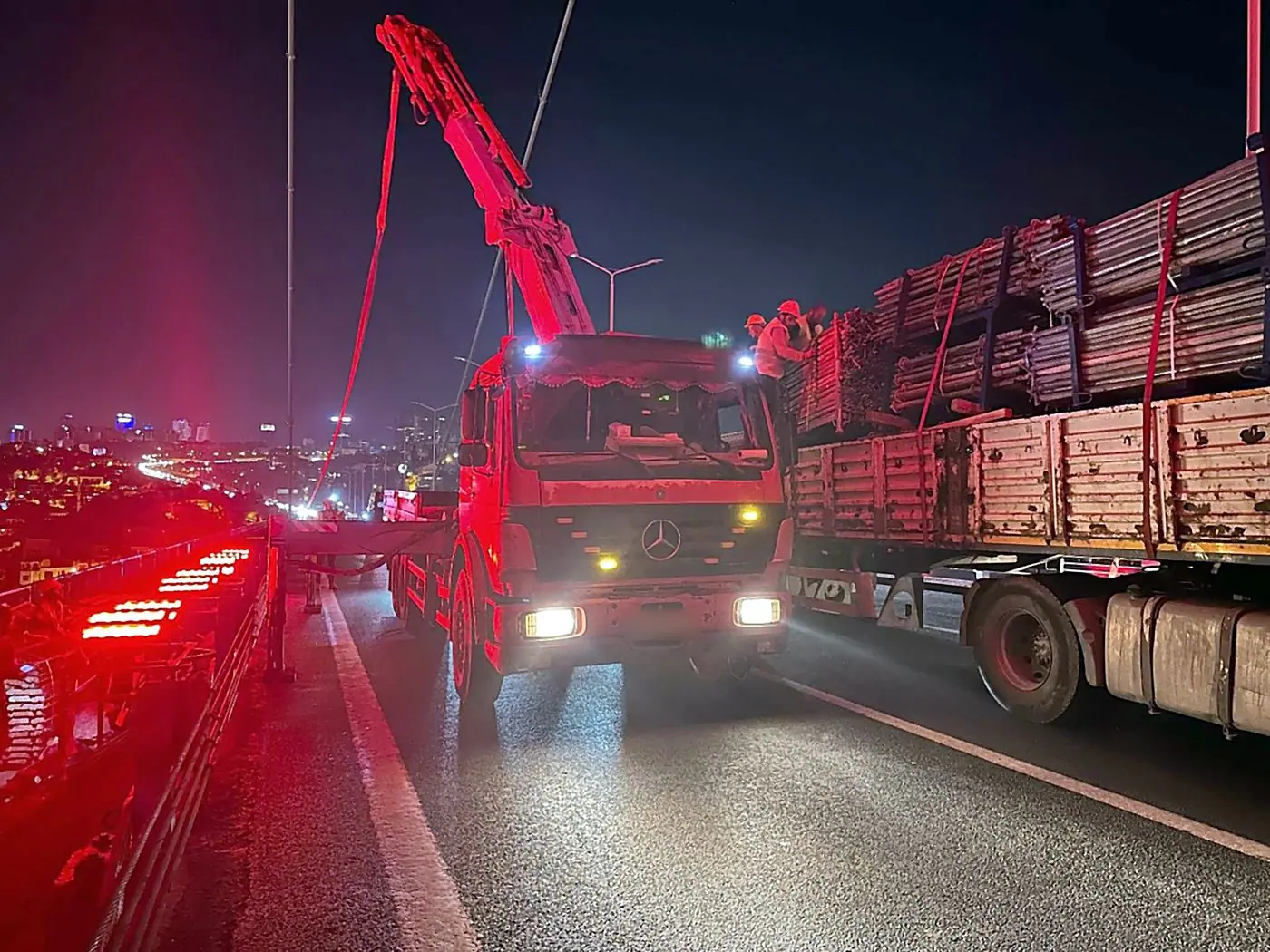
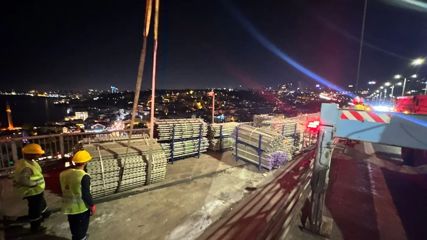
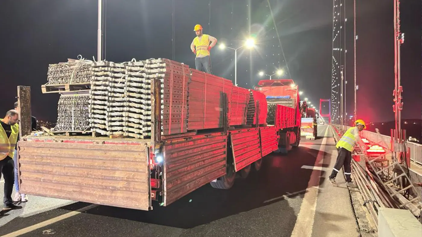
Download catalogue (PDF) · 5.1 MB All catalogues15 July Martyrs Bridge · Limak · Istanbul
Frequently asked questions
Where is ringlock scaffolding used?
In power plants, refineries, tanks, shipyards, bridges and complex facades - both as working scaffold and as shoring.
What load can a ringlock standard carry?
Up to 6 tons per standard depending on the configuration; the exact value is determined by structural calculation.
How do you calculate the ringlock quantity?
We derive bays and lifts from width and height and calculate standards, ledgers, diagonals, decks and jacks. Enter your dimensions in the quote form for an automatic preliminary calculation.