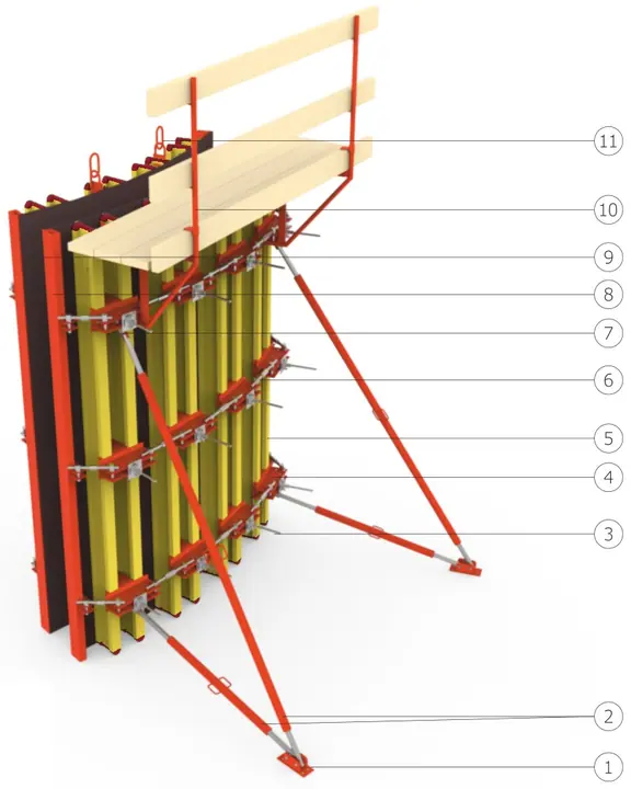
Table & Shoring Scaffolding System
High load capacity and short cycle times for concrete slabs.
- 25 components
- 72 size options
- 150 × 120-200 cm Frame
- Ø60 × 3-4 mm Tube
About the Table & Shoring Scaffolding System
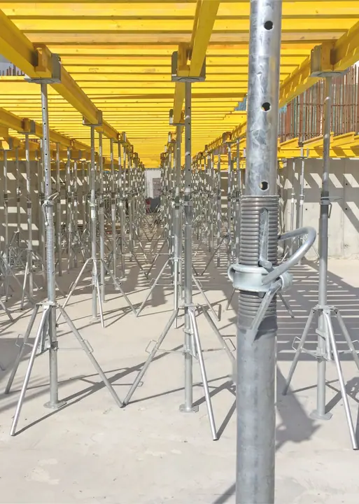
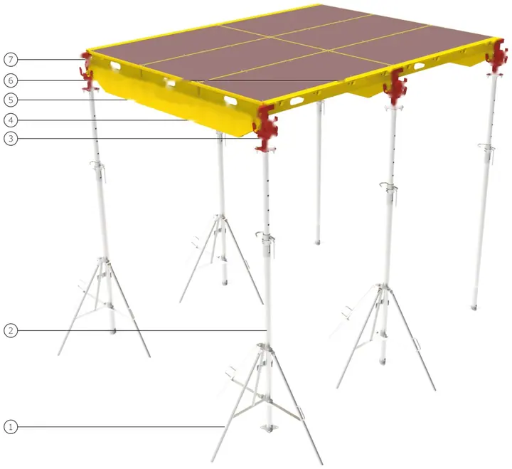
BLC Table & Shoring Scaffolding is a temporary support system that safely carries the formwork while pouring concrete slabs and beams. High-capacity frames with adjustable base and head jacks adapt quickly to different storey heights, and together with H20 timber beams form a flat and safe formwork surface. Fast assembly and dismantling save time and cost on site.
Key features
- Ø60 mm frames with 3 mm / 4 mm wall thickness
- Precise level adjustment with base & head jacks
- Four-way head compatible with H20 timber beams
- Fast cycles with table carrier and lifting fork
- Modular frame sizes: 150×120 / 150 / 180 / 200
- Painted or galvanized finish options
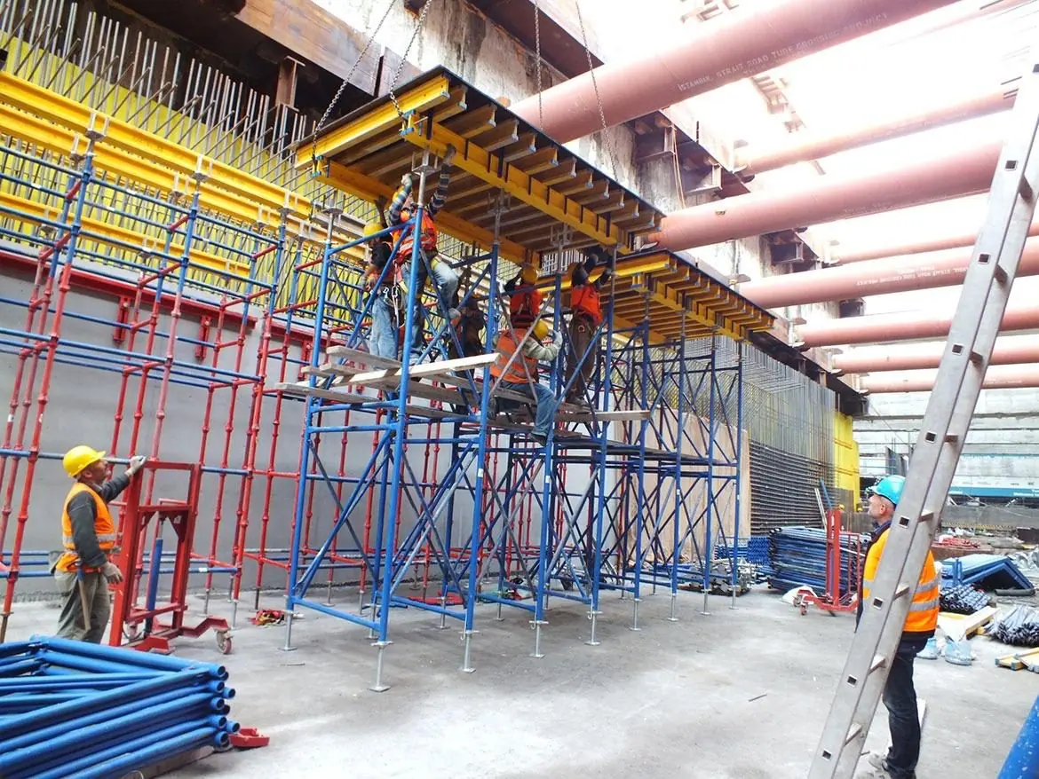
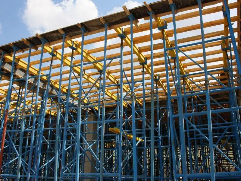
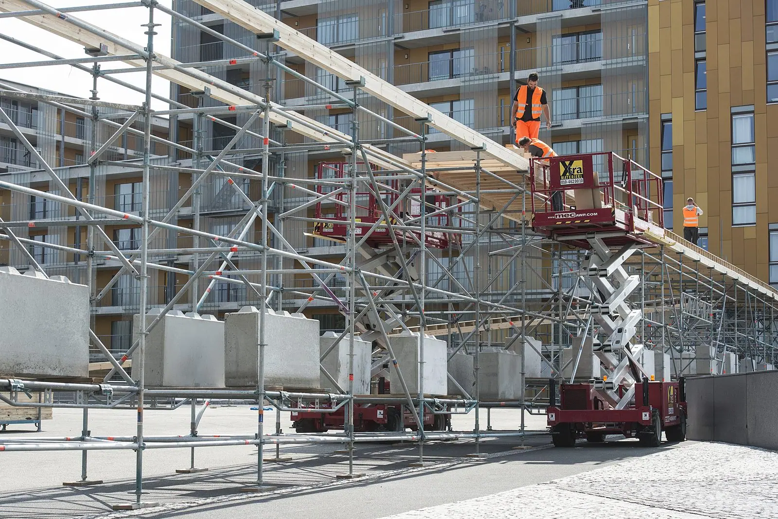
System components
Click a component for its size and weight table.
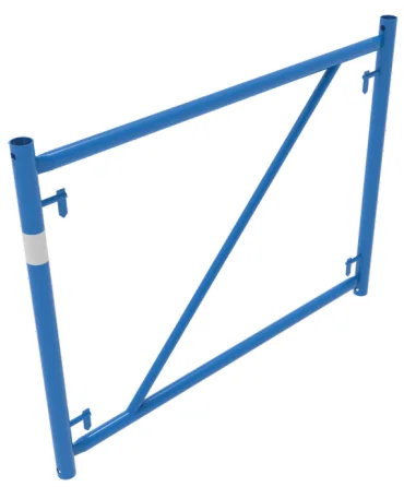
Frame 150/120
150/120 … 150/120 · 19.5–22.6 kg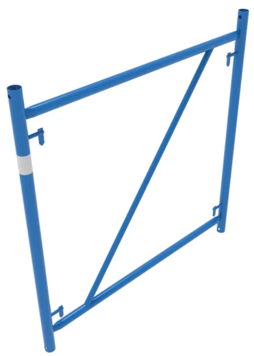
Frame 150/150
150/150 … 150/150 · 22.1–26.1 kg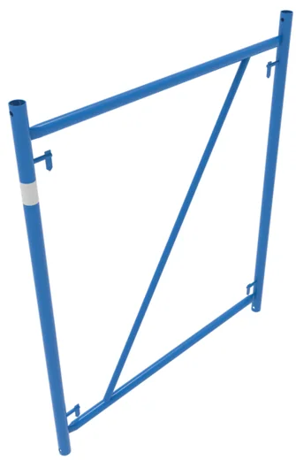
Frame 150/180
150/180 … 150/180 · 24.8–29.5 kg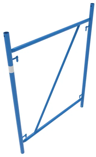
Frame 150/200
150/200 … 150/200 · 26.4–31.7 kg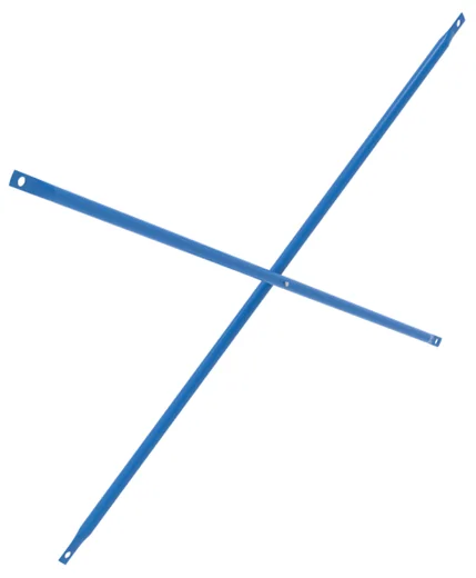
Diagonal
120/100 … 180-200/250 · 4–8.7 kg
Jack Ø48
80–120 cm · 3.7–5.8 kg
Base Jack Ø48
80–120 cm · 4.75–7.7 kg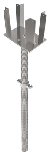
H20 Head Jack Ø48
80–120 cm · 9.1–11.3 kg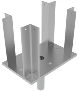
Head - H20
4.3 kg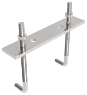
Head - H20 Coupler
1.2 kg
Girder Connector
40 cm · 0.5 kg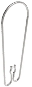
Jack Hook
0.1 kg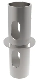
Scaffold Connection Ø60
0.5 kg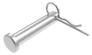
Pin and Split Pin
10×65 … 16×80 · 0.06–0.15 kg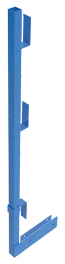
Table Guardrail
145 cm · 6.9 kg
Table Guardrail Compressible
145 cm · 7.2 kg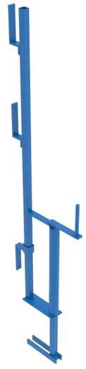
Compressible Slab Guardrail
145 cm · 8 kg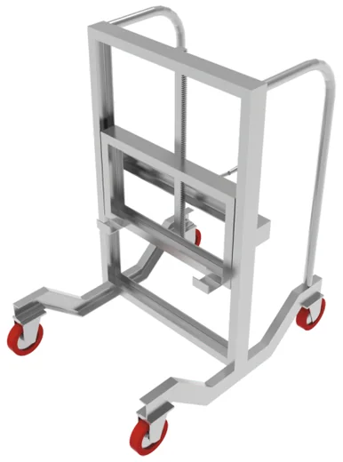
Table Carrier
162 kg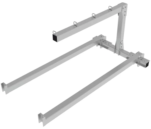
Table Lifting Component
230 kg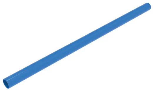
Tube Ø48×2.5
100–600 cm · 2.55–15.4 kg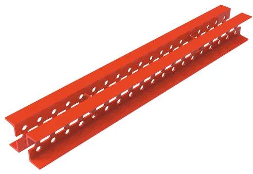
Universal Steel Waler
70–595 cm · 17.5–148.75 kg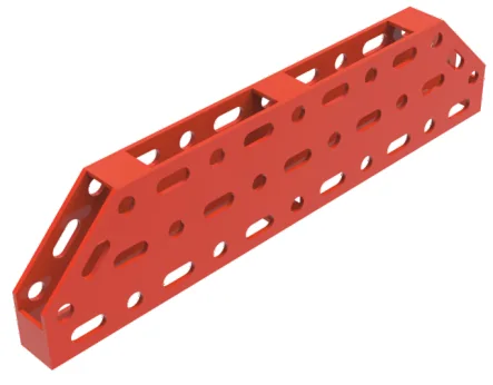
Universal Steel Waler Coupler
75 cm · 13 kg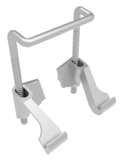
Universal Waler Hook
1 kg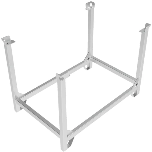
Storage Cage - Opened Type
120×78×83 · 49 kg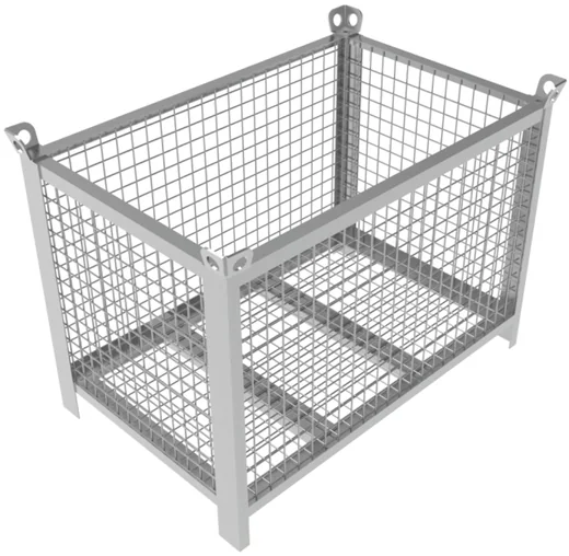
Storage Cage - Mesh Type
120×78×83 · 70 kgErection sequence
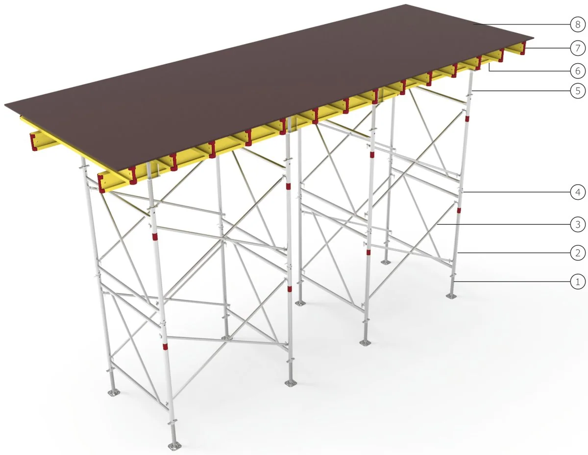
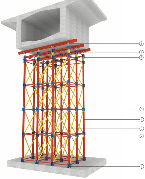
General view
- Base Jack Ø48
- Shoring Frame
- Diagonal
- Scaffold Connection Ø60
- H20 Head Jack
- Main Beam - H20
- Secondary Beam - H20
- Plywood
- Position and height of the base jacks are set according to the shoring plan.
- The first level frames are mounted on the base jacks.
- Diagonals are fitted and the first level is completed.
- Connection spigots are inserted into the frames.
- Second level frames are placed and fixed to the first level with pins and split pins.
- Diagonals of the second level are fitted.
- The steps are repeated up to the design height.
- The height of the H20 head jacks is adjusted according to the design.
- Main H20 beams are placed according to their length and overlaps, followed by the secondary beams.
- The system is completed by laying the plywood.
Application notes
- Frame and jack loads must be checked by calculation according to slab thickness.
- Jacks must not be extended beyond the design length.
- Erection, dismantling and modifications must only be carried out by trained, certified crews according to the approved design.
- Damaged, deformed or incomplete components must never be used.
- The ground must be level, firm and capable of carrying the loads.
- The system must be inspected by a competent person after erection, at regular intervals, after any modification and after adverse weather.
- Local regulations and occupational health & safety rules must be followed.

Table & Shoring Scaffolding System catalogue
System introduction, size and weight tables of all components, erection sequence and technical data in a single PDF. Turkish / English.
Download catalogue (PDF) · 4.3 MB All cataloguesSlab and shoring applications · Table scaffolds, shoring and props
Frequently asked questions
What is the difference between table and shoring scaffolds?
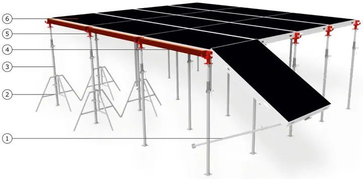
Both use the same frames; table scaffolds are moved to the next slab by crane or carrier without dismantling, saving time and labour.
Which frame sizes are available?
150 cm wide frames in 120 - 150 - 180 - 200 cm heights; Ø60 mm tube with 3 mm or 4 mm wall.