FORMWORK & SHORING SYSTEMS
Heavy Duty Shoring System
A universal shoring system for bridges, viaducts and heavy slabs.
- 15 components
- 46 size options
HDS
About the Heavy Duty Shoring System
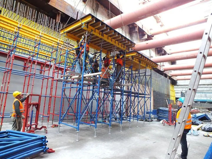
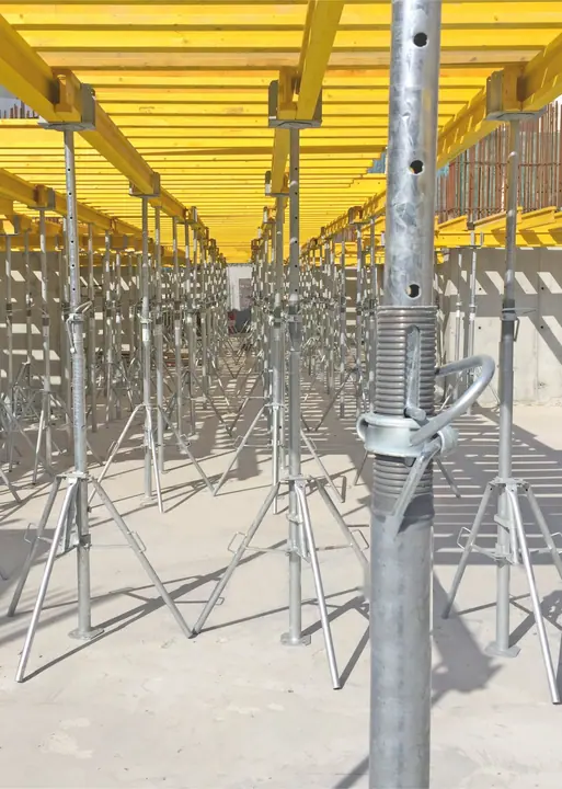
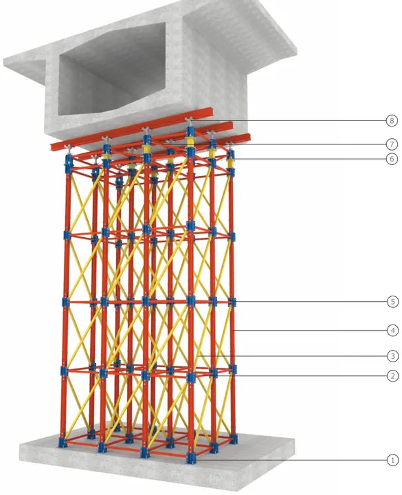
BLC Heavy Duty Shoring System is a universal shoring system designed for bridges, viaducts, tunnels and slabs requiring high loads. Towers, beams and support structures of the required height and span are formed with shoring beams, end and connection components; precise height adjustment is made with a hydraulic pump.
Key features
- High capacity for bridge and viaduct formwork
- Modular beams and connectors
- Large spans with main rails
- Adjustment with 400 kN hydraulic pump
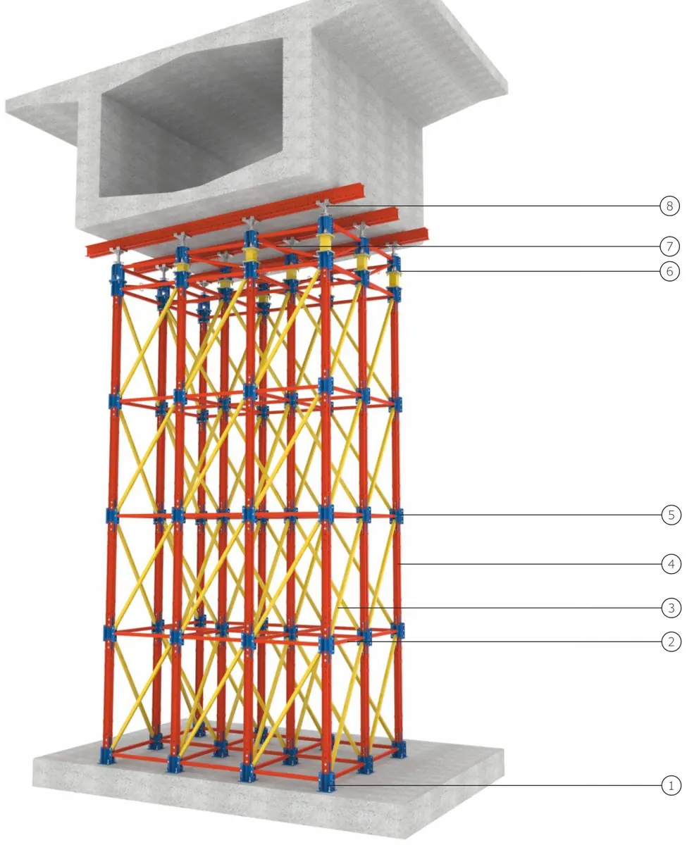
Heavy Duty Shoring System
System components
Click a component for its size and weight table.
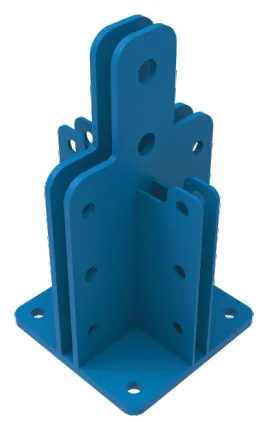
End Component
21.3 kg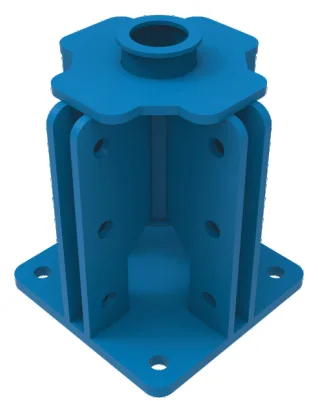
Jack Connector
17.6 kg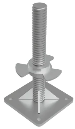
Jack Base
50 cm · 16 kg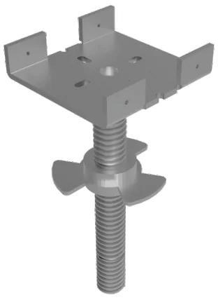
Jack Head
50 cm · 16 kg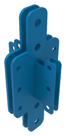
Beam Connector
16 kg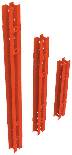
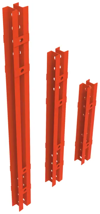
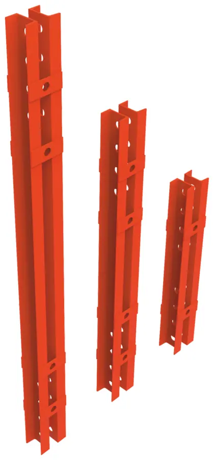
Shoring Beam
95–195 cm · 20.9–42.9 kg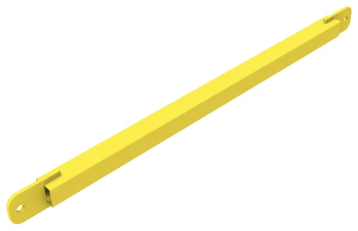
Ledger
50–250 cm · 1.9–12.7 kg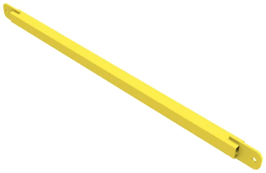
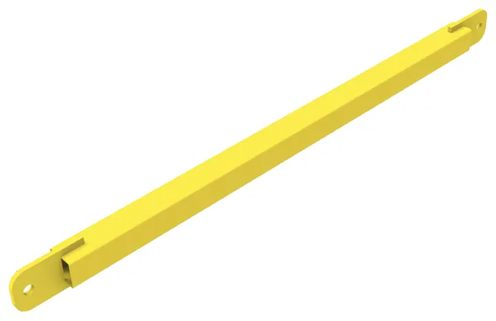
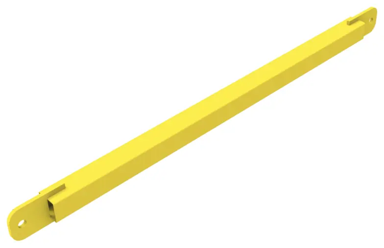
Diagonal
50-100 … 250-200 · 5.5–16 kg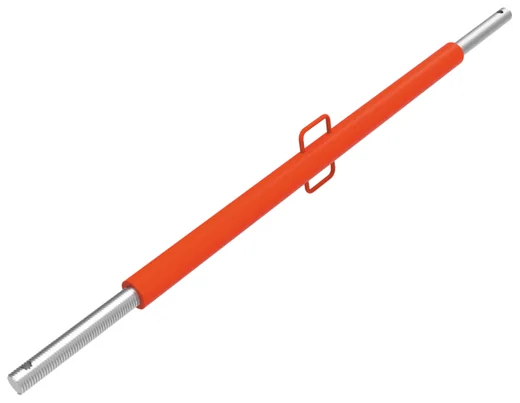
Push-Pull Prop
50–200 cm · 9.9–16.5 kg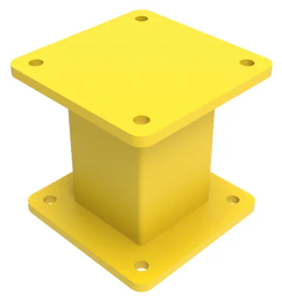
Height Adjustment
10–30 cm · 17.2–27.1 kg
Main Rail
200–600 cm · 100–300 kg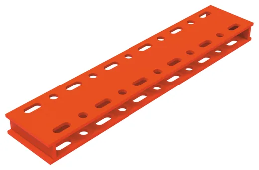
Main Rail Connector
75 cm · 14.4 kg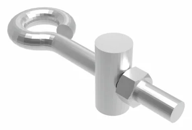
Main Rail Connection Pin
0.5 kg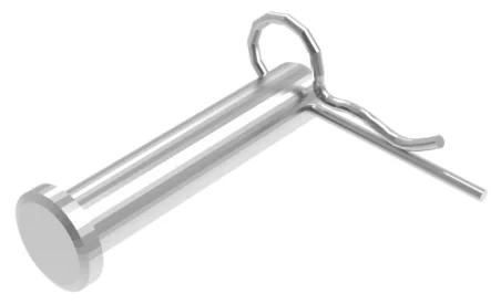
Pin and Split Pin
20×130 … 30×100 · 0.3–0.6 kg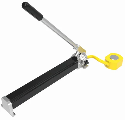
Hydraulic Pump 400 kN
15 (ayar mesafesi) · 25 kg
Heavy Duty Shoring System
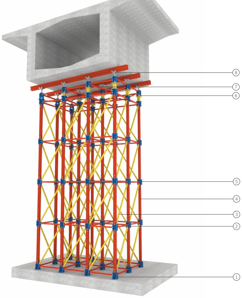
Erection sequence
General view
- End Component
- Ledger
- Diagonal
- Shoring Beam
- Beam Connector
- Jack Connector
- Push-Pull Prop
- Jack Head
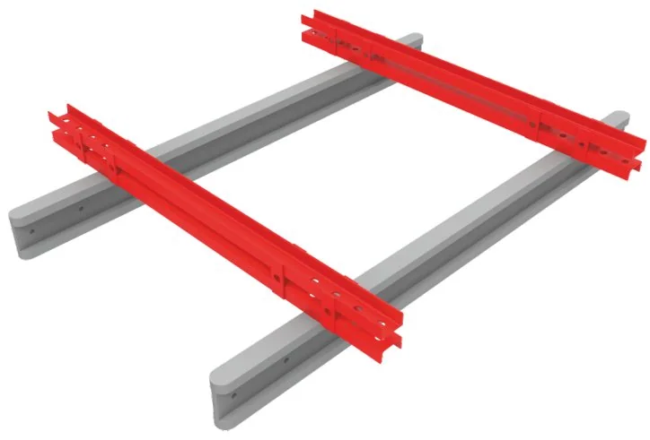
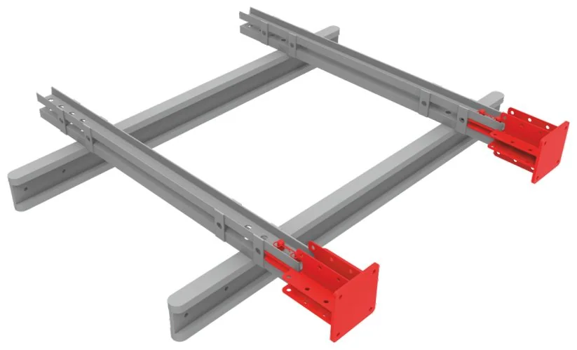
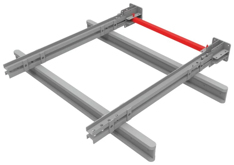
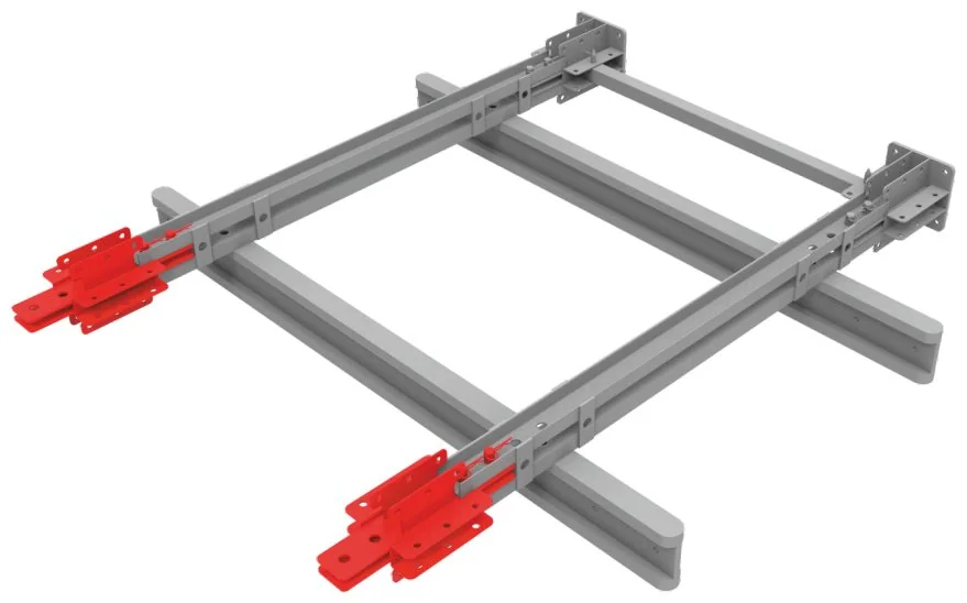
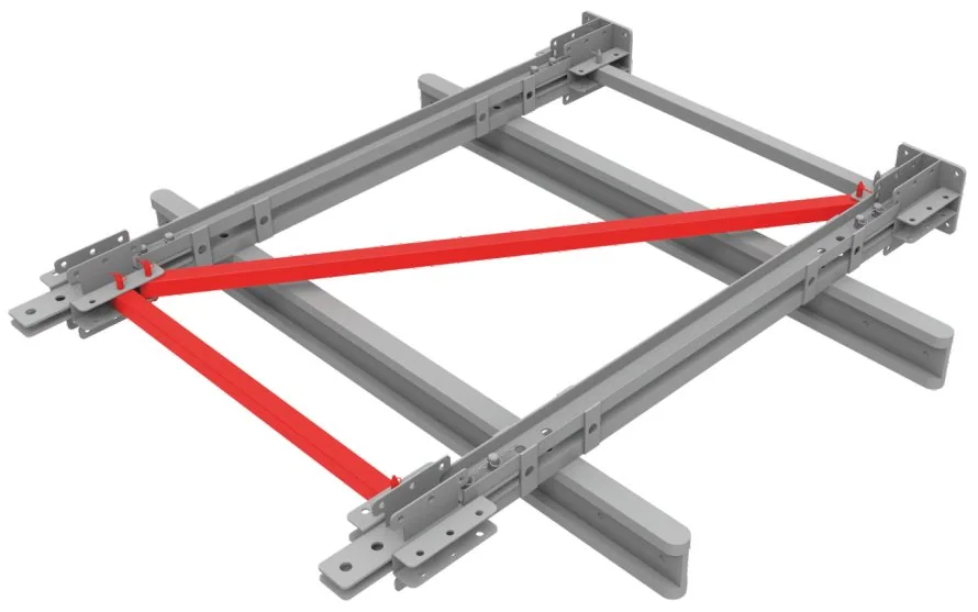
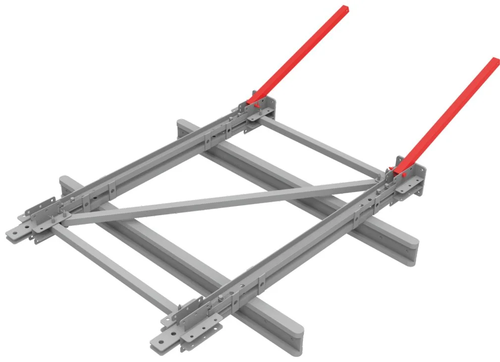
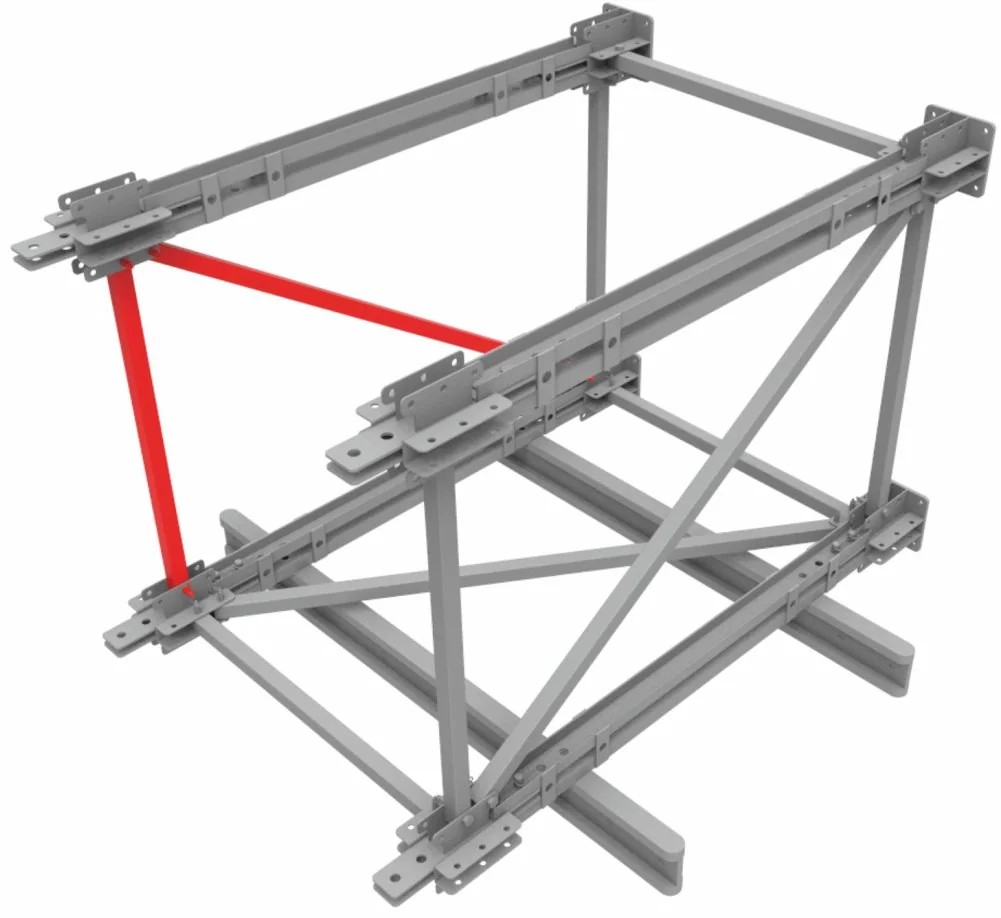
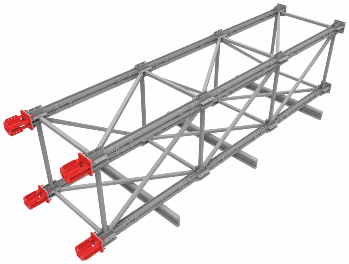
- The assembly area must be flat; main beams are laid on H20 beams approx. 20 cm above the ground.
- End components are fixed to the beams with two 30×100 pins and split pins each.
- Ledgers are fitted between the end components with 20×130 pins and split pins.
- Beam connectors are fixed to the beams with 30×100 pins and split pins.
- Diagonals and ledgers are fitted between the end components and beam connectors.
- To build the tower, ledgers in the other direction are fitted vertically and upper end components placed.
- Upper beams and connectors are fitted; diagonals are arranged in a spiral pattern.
- Additional tower sections are added in the same sequence according to the assembly drawings.
- Jack connectors are bolted to the tower end with M20×40 bolts and connected with ledgers.
- The tower is lifted into place by crane, braced with push-pull props and levelled with the jacks.
Application notes
- Tower height, spans and loads are set by the structural design; fine adjustment with a hydraulic pump.
- Erection, dismantling and modifications must only be carried out by trained, certified crews according to the approved design.
- Damaged, deformed or incomplete components must never be used.
- The ground must be level, firm and capable of carrying the loads.
- The system must be inspected by a competent person after erection, at regular intervals, after any modification and after adverse weather.
- Local regulations and occupational health & safety rules must be followed.

Catalogues
Heavy Duty Shoring System catalogue
System introduction, size and weight tables of all components, erection sequence and technical data in a single PDF. Turkish / English.
Download catalogue (PDF) · 4.4 MB All catalogues